Thursday, June 17, 2010
Wednesday, June 16, 2010
Week 18
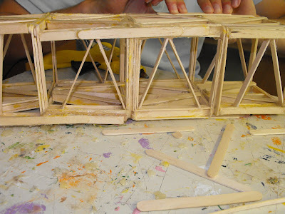
Tuesday- Today we are still working on our crane. We Finished our third box and started working on our fourth. Jeremy started working on the Top Trusses of the crane. He made it mostly out of ibeams and then basic popsicle sticks.
Wednesday- Today we uploaded our Research and slideshows to our blogger. And then we also added our AutCad drawings for evaluation.
Thursday- Today we finished our crane base and top part.
Friday- Today was an exam day and we added our support beams to hold up the top
Tuesday, June 15, 2010
Wednesday, June 9, 2010
Monday, June 7, 2010
Week 17
Tuesday - Was not Present
Wednesday- Today i put all of my drawings in title blog and then added them to my blog, I then started building our Crane. Today was shortened periods.
Thursday- Today i was not Present. My group started the crane
Friday- Today i was not Present.
Tuesday, June 1, 2010
Week 16
Tuesday - Today i started on the top of my crane doing it in triangle Ibeams. Then i had to add my counter weight in to AutoCad. I am almost finished then i will be able to pick groups.
Wednesday - Today i continued to do my crane on Autocad. I had to make supportbeams for the top of the crane. To do so i had to make to diagonal trusses going to the top part of the crane and then i put triangles within the beams to create extra support
Thursday- Today i added my measurements for the crane. I put measurements for all the neccessary lines that we needed to know. I then started my orthographic drawings. Tommorrow i will have to finish those and then add measurements to them
Friday - Today i continued on my orthographic drawing, i still have not finished, i need to do all three views of the base and the top of the crane. It is very difficult and time consuming.
Monday, May 31, 2010
Group Problem Solving
- Dont jump to solutions bedfore defining the problem.
- solve problems close to the source
- attend to the interests of all stake holders
- Team-based knowledge driving systems change
Skills-
- Brainstorming
- faciliation
- Process improvement
Brainstorming Guidelines-
- Identify a recorder and facilitator (can be the same person)
Clarify the issue or question - If appropriate, first generate ideas individually on paper
- Begin recording ideas from the group --sequentially or otherwise
- Encourage “piggy-backing” and “wild or crazy” ideas
- Discourage criticism or judgmental comments
- Push past “the pause”
- Cluster before you prioritize
A Process Improvement Model
Aim (The aim of the process --How are things supposed to happen?)
Reality (How do things actually happen?)
Root Causes (What would account for any gaps between the aim and reality?)
Improvement Options (What are options that might help close the gap?)
Value-added Implementation (Of the many options, which ones will add value? How would they be implemented?)
Evaluation and Continuous Improvement (What are the criteria for success? What is the evaluation plan? What mechanisms will help ensure continuous improvement?)
Source: Valuable Disconnects by Joel Cutcher-Gershenfeld and Kevin Ford
Thursday, May 27, 2010
Week 15
Tuesday - Wasn't Absent.
Wednesday- I had to write the test today and then i had to continue my research for my crane project. i had to put all of the information into a slide show with a minimum of fifteen slides. I did not finish that today, i will have to conitinue it tommorrow
Thursday - Today i finished my slideshow with my reasearch on Tower Cranes. I will next have to start my individual AutoCad drawing of my tower crane plan. This project is going to be fun.
Friday - Today we continued to work on AutoCad, i came up with my own design using Ibeams. My design i think will be very succesfull i did not finish my full box yet. I will have to finish it on monday.
Thursday, May 20, 2010
Crane Research
- Large anchor bolts embedded deep into this pad support the base of the crane. cranes are essentially bolted to the ground to ensure their stability
- The crane cannot lift that much of weight if load is at the end of the jib. the closer the loads is positioned to the mast the more weight the crance can lift saftley.
- The tower crane is a modern form of balance crane. Fixed to the ground (or “jacked up” and supported by the structure as the structure is being built), tower cranes often give the best combination of height and lifting capacity and are used in the construction of tall buildings. To save space and to provide stability the vertical part of the crane is often braced onto the completed structure which is normally the concrete lift shaft in the center of the building. A horizontal boom is balanced asymmetrically across the top of the tower. Its short arm carries a counterweight of concrete blocks, and its long arm carries the lifting gear. The crane operator either sits in a cabin at the top of the tower or controls the crane by radio remote control from the ground, usually standing near the load. In the first case the operator’s cabin is located at the top of the tower just below the horizontal boom. The boom is mounted on a slewing bearing and is rotated by means of a slewing motor. The lifting hook is operated by a system of sheaves.
- In order for a crane to be stable, the sum of all moments about any point such as the base of the crane must equate to zero. In practice, the magnitude of load that is permitted to be lifted the “is some value less than the load that will cause the crane to tip.
The Engineering Design Process
- Problem identification
- Research Phase
- Requirements Specification
- Concept Generation
- Design Phase
- Prototyping Phase
- System Integration
- Maintenance Phase
- Collect Information
- Interpret information
- Organize needs hierarchy
- Determine relative importance of needs
- Review outcomes and process
Examples: Need: Drivers have difficulty seeing obstructions in all directions
Objective: Design system to avoid accidents.
Concept Generation and Evalution:
- Explore Many Solutions - Brainstorm
- Select the Best Solution - based on needs and constraints
- Creativity- Development of new ideas
- Innovation - Bringing creative ideas to reality.
Concept Generation:
- Substitue
- Combine
- Adapt
- Modify
- Put to other use
- Eliminate
- Rearrange or reverse
Decision Making Guidelines:
- Decision by authority(leader)
- Expert Member
- Average Member Opinion
- Majority
- Consensus
Project Management:
- Work to be done
- Timeframe
- Rescources Needed
- Responsible Person
- Previous dependent activities
- Checkpoints/Deliverables for monitoring progress
Wednesday, May 19, 2010
Tuesday, May 18, 2010
Sectional Drawing Test Review
Assembly Drawings -> used to show the position and functional relationship parts in an assembly.
They have no dimensions.
Section Views ->are used to clarify internal detail and to avoid dimensioning to hidden lines. They are established by refrencing a cutting plane. They depict the exact location on the part from which the section view will be projected, and should have associated arrowheads, indication the direction from which the section view will be observed. Cutting planes are constructed as an integral feature of the parent view, and cutting plane arrowheas always indicate the direction for the observers line of sight.
Cross Hatching -> a repeating graohic pattern which is applied throughout all areas of the part that would be in contact with the cutting plane. . The recommended angle for the standard cross hatch patter is 45,30,60 degress horizontal.
Half Sections -> views are the result of cutting planes being positioned on parts in such a manner that only half of the resulting view or projection is show in section. Used on objects of symmetry.
Offset Sections-> allows us to provide greater breadth of detail with fewer section views. all of the features are aligned with the cutting plane.
Week 14
Tuesday - Today we did a note on sectional drawings, then we had to make sure our logs where up to date with everything loaded onto them and all of our journals done.
Wednesday- Today we did three quizzes in chapter 8 on Architectural drawings for Auto Cad. We did them for review for our test tommorrow. If we do not have the test tommorrow we will be having it on tuesday after Victoria Day. After that we got our crane project and i searched collapsing cranes on youtube.com.
Thursday - Today was dress down day. We did a note on engineering and its whole purpose was to guide us along in our Crane Project. Then after that we had to do research for our crane project. We had to research different ideas and information on how a crane works
Friday - Today I was at Skills Canada
Monday, May 17, 2010
Monday, May 10, 2010
Week 13
Tuesday- Today I handed in my orthographic drawings with the corrections done to them. Then we got our final cad drawing, and it seems challenging. We have to do a control bracket. First i started with the grid then did the limits to 150,200. They seem reasonable. Then i started the front view however I am not finished just yet.
Wednesday- Today i continued my final Cad Drawing i did the right side view and the top view. It was very challenging because we had to learn new commanads to make a hexagon. Which was "poly". I will have to add all of my dimensions and hidden lines tommorrow.
Thursday - Today i added the hidden lines to my Final Cad drawing, i still have to add the ceneter lines and the dimensions then i will be done.
Friday - Today i finished up my Final Autocad drawing. this drawing was harder then most of the other ones we have done
Thursday, May 6, 2010
Wednesday, May 5, 2010
Week 12
Tuesday - Today we learned more about orthographic drawings. Then we continued on the AutoCad orhtographic drawings. Today i only started the second piece which is the right view. I will soon have to add then hidden lines and the dimensions , and then post it onto blogger.
Wednesday- Today i continued to work on my vertical brace in AutoCad. I finished the drawing and then had to finish the measurements because they where on the right view instead of the front view. I then had to change the spacing of how far the views were from eachother. After that i had to change my limits because my right side view was going off the page.
Thursday- Today i put my vertical brace onto paper in AutoCad and uploaded it onto blogger, then i updated my journal from yesterday. After this i was done all of my assignments.
Friday - Was not present, was in Toronto at OCAD
Thursday, April 29, 2010
Wednesday, April 28, 2010
Monday, April 26, 2010
week 11
Tuesday - Today i continued on my electrical drawing on AutoCad. I added the dimensions and the hidden lines along with the center lines. I had to adjust some measurements and then lines because i did not put the appropriate lines in . I needed Hidden and Center lines.
Wednesday- Today i finally finished the electrical drawing and added all of the dimensions in a yellow line. Then I uploaded it onto blogger.
Thursday- Today i started my star drawing on AutoCad. I then finished it and then i added the dimensions and the hidden lines along with the center lines. I had to adjust some measurements and then lines because the lines did no match up with the picture.
Friday - Was at sheridan for a school trip
Mechanical Drafting
Two methods - Aligned and unidirectional
* Do not place dimensions on objects, Do not dimension to hidden lines.
Thursday, April 22, 2010
Tuesday, April 20, 2010
Monday, April 19, 2010
Week 10
Tuesday- Today I finished doing my Gasket drawing in autcad and I put it onto the white sheet. I added my name and the name of the assignment. then later i posted it onto my blog. After that Mr.D came over and marked my Animation of my house design. Then he talked to me about different schools for interior design.
Wednesday- Today we got assigned AutoCad quizzes, we have 20 of them to do and they have to be done by Friday April,23rd. After we complete all of the quizzes we will have an AutoCad test. Then i also worked on my Outlet mechanical drawing in AutoCad. I made the squares and circles looking at the example that is posted on Moodle.
Thursday - Today i finished up all of the Auto Cad quizzes and posted them on my blog in their own post. Then i continued to work on my AutoCad mechanical drawing of the outlet. I worked on the second and third shape of the drawings. Tommorrow i should be working on dimensions and putting it onto the white paper.
Friday -
Thursday, April 15, 2010
Wednesday, April 14, 2010
What I Learned From This Project
Over all I liked this project. However there are a couple things I would like to change. I wish we could have had more square footage to work with because our maximum was 2000 Sq Ft. I also think it would be really great if we could have done more then one floor. Overall I wish we had more time for more details and a better done project.
In all I was pretty comfortable with the program , and I think I covered all of the essential skills very well. I did not have any trouble with this assignment, in fact I enjoyed it. However I could use some work in my measurements, that was the only thing that sort of confused me, but i was pretty comfortable with it. To accomplish this I think I just need to practice more drawings with measurements so I can understand it throughly
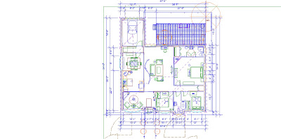
House Measurements

Area:19'-1" x 10'-2"
Sqaure Feet:194.01
Kitchen
Area:11'-9" x 12'-3"
Sqaure Feet:143.93
Dining Room
Area:10'-1" x 12'-1"
Sqaure Feet:121.84
Laundry Room
Area:3'-9" x 11'-9"
Sqaure Ft:44.06
Living Room
Area:25'-2" x 16'-9"
Sqaure Feet:421.54
Bedroom 1
Area:11'-4" x 9'-11"
Sqaure Feet:112.38
Bedroom 2
Area:10'-2" x 12'-9"
Sqaure Feet:129.62
Master Bedroom
Area22'-4" x 16'-9"
Sqaure Ft:374.08
Bathroom
area:10'-5" x 6'-4"
Sq Ft:65.97
TOTAL: 1607.43


